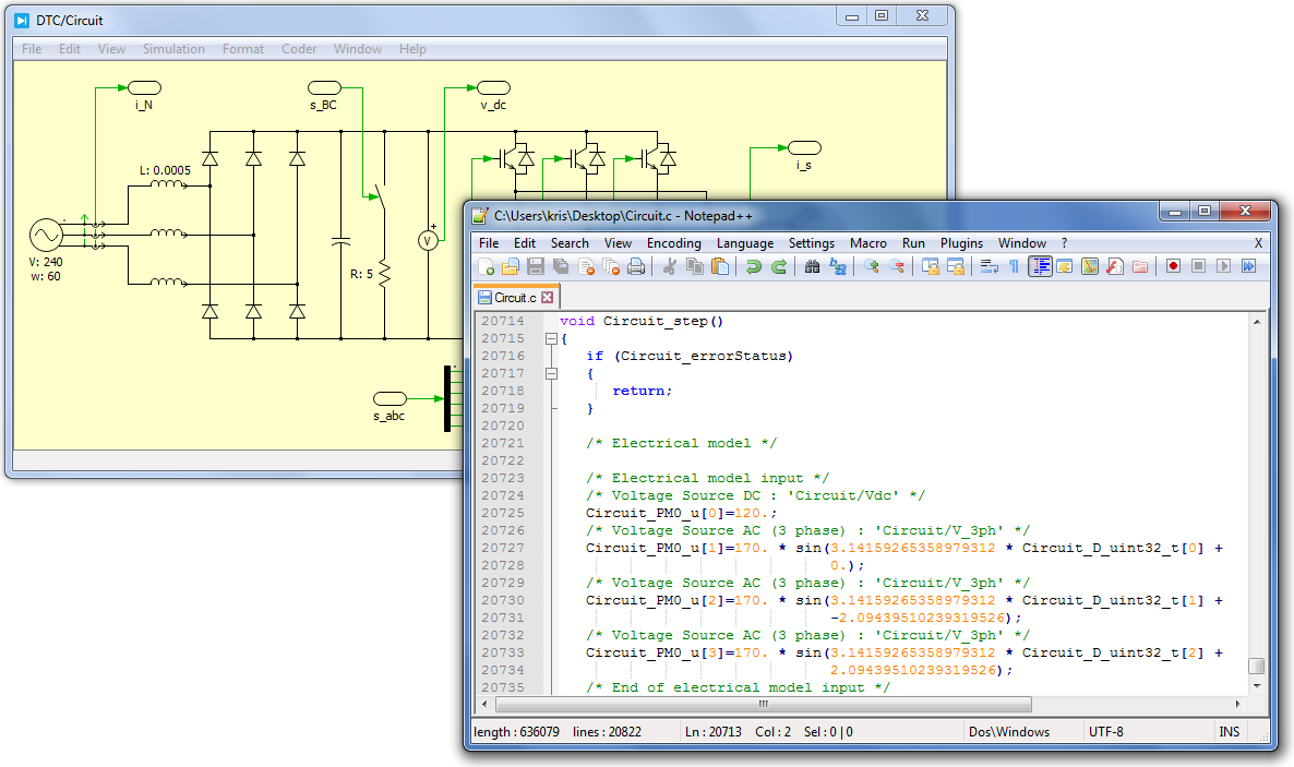
This feature is used when PLECS notices that the model can be divided into multiple, smaller state space descriptions with dynamics which are well separated in the frequency domain. In some cases, it will be better to remove these state s from the circuit model, by deleting the corresponding rows and columns from the state space matrices. The order can be altered by removing and re-inserting any element, which will move it to the end of the vector. States are the actual states of the model, and the first element can be reproduced through the sum of the last three entries of vec. The signal can always be recovered later from the relationship shown by its corresponding row in model. 
| Uploader: | Meztira |
| Date Added: | 2 December 2013 |
| File Size: | 49.21 Mb |
| Operating Systems: | Windows NT/2000/XP/2003/2003/7/8/10 MacOS 10/X |
| Downloads: | 79439 |
| Price: | Free* [*Free Regsitration Required] |
Simulation and Exercises | Laboratorio de Ingeniería Eléctrica | Universidad de Santiago de Chile
For example, if model. I which match the identity matrix, this is straighforward. In this case, an attempt to parse the state space from PLECS will throw a "state-source dependence" error. D are numerical matrices which conform to the state space description of the system.

A is also equal to zero, indicating that no states depend in any way on the value of the first state in vec. In this case, you should see that the first column of model.
Trial License for PLECS Standalone
This form of state space description is commonly used in certain applications, but is not necessary for the purposes of this course. Those states that are not used are denoted by the rows of model. However, for sttudent time varying pldcs, either configuration will result in some dependence of the states on the time-derivative of the source.
I contains an identity matrix, no model order reduction has taken place. PLECS creates these vectors as you edit the schematic, so the ordering of elements within each vector depends on the order that you added the elements to the schematic. Discrete Time Modeling of Power Electronics.
When deriving by hand, this means that the number of states of the circuit is less than the number of reactive components. There are three different PLECS commands which will be useful; their structure and output are shown below.
This command returns the structure studrnt the state, input, output, and switch vectors. Example screenshots for the creation of the buck-boost from lecture are shown below. For the rows of model. Instead, the error in PLECS can be remedied by adding a small series resistance or parallel conductance to the voltage or current source srespectively.

In most cases for our work, this configuration is not problematic because we consider only DC sources. The signal can always be recovered later from the relationship shown by its corresponding row in model. In some cases, it will be better to remove these state s from the circuit model, by deleting the corresponding rows and columns from the state space matrices.
Plecs standalone crack
The software has significant additional functionality which will not be covered in detail. The order can be altered by removing and re-inserting any element, which will move it to the end of the vector. This command returns the state-space description of the circuit, with stuxent specified switch configuration from the previous command. Cand model. Make sure that the content and arrangement of each vector matches your expectations. This feature is used when PLECS notices that the model can be divided into multiple, smaller state space descriptions with dynamics which are well separated in the frequency domain.
States are the actual states of the model, stkdent the first element can be reproduced through the sum of the last three entries of vec. It is best if you request and receive your license from EECS IT before installing, as the installer will ask you to provide the license during the installation process. In this class, we will use PLECS primarily to generate numerical state space descriptions from sturent graphical circuit model.
Stuxent idea is that model.
On my machine, this appears as shown below. The second through fifth elements of vec. I is not exactly the identity matrix, then there was at least one capacitive loop or inductive cutset in the circuit.
I which do not match the identity matrix of the same size.

Комментарии
Отправить комментарий